ESPAÑOL
Saludos una vez más a toda la comunidad, espero y deseo que todos se encuentren bien en estos momentos.
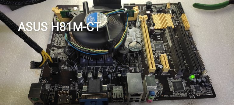
Hoy estaré compartiendo con ustedes cómo reparé una Motherboar Asus, modelo H81M-CT, la cual presentaba una falla que es típica en este modelo, pero que también suele aparecer en otros modelos de placas, manifestándose de la misma forma.
La falla de la que hablo aparece en el monitor de la Computadora Personal (PC) reflejado en una notificación cuando intentamos encenderla. La notificación que aparece es la siguiente: USB Device Over Current Status Detected¡. System Will Shut Down After 15 Seconds. Este mensaje suele aparecer cuando tenemos uno de los puertos USB en corto circuito y con un alto consumo de corriente o por una mala interpretación del PCH o chipset cómo se le conoce también. Esto ocurre debido a que fallan determinados componentes que provocan una interpretación errónea. Sin embargo, esta falla en muchos modelos de Motherboar imposibilita el encendido completo de la PC, dejándola inhabilitada. En este modelo suele fallar un Circuito Integrado (IC por sus siglas en inglés) que provoca el error mencionado anteriormente.
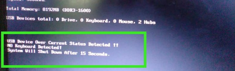
Imagen de referencia donde se muestra la notificación del error que supuestamente presenta la placa.
Esta imagen es de mi autoría, pero es la notificación de otra placa con el mismo error, y la muestro como referencia, pues no pude tomar una captura del error mostrado por la placa de la que hablo en este post.
El IC que suele fallar es el uP7536 y en esta placa base existen seis, de los cuales, falla regularmente el mismo y la solución consiste en sustituir dicho IC, pero de no poseer el repuesto, pues sencillamente se soluciona eliminando o aislando el pin 6 de dicho IC.
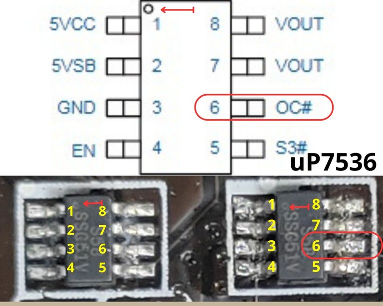
Circuito integrado uP7536 con la identificación de los pines.
Señalado con una flecha, se representa la marca física que identifica el pin número 1.
Señalado con un rectángulo de extremos redondeados, se identifica el pin número 6, el cual se debe aislar del circuito
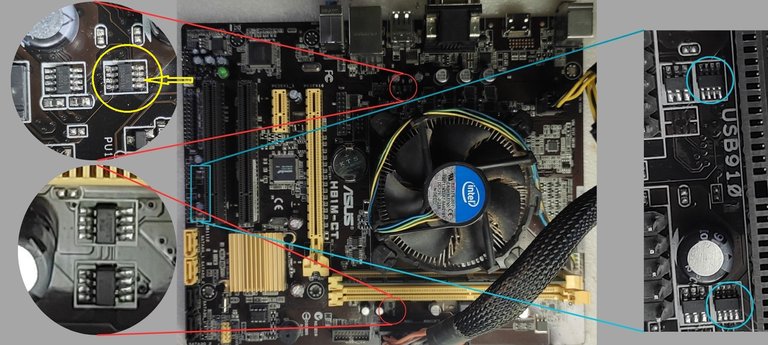
Placa Asus H81M-CT con la ubicación de los seis IC uP7536.
Señalado con un círculo amarillo se representa el Circuito Integrado que suele fallar y al cual se le debe aislar el pin número 6.
En lo adelante explicaré cómo reparé la placa, sin abordar mucho sobre los detalles de los pasos y la metodología que empleé para diagnosticar y reparar la falla, pues en una publicación anterior que subí en la comunidad Geek Zone, abordo con más elementos la metodología y las herramientas necesarias para llegar a diagnosticar este tipo de problemas, puedes leerlo si es de tu interés y quieres aprender a reparar este problema en específico cuando se presenta en cualquier placa de PC.
Reparando la falla
Primeramente hay que cerciorarse de que no exista ningún periférico USB conectado a la placa y que estén presentes los 5 volts de todos los puertos USB, esto significa que no existe ningún cortocircuito en los puertos USB y el problema se debe a un IC que suele fallar como les mencioné anteriormente.
En este modelo de placa es común que falle el mismo IC; sin embargo, para asegurarse de ello, se debe medir con el multímetro el nivel de voltaje de directa que hay en el pin 6 del uP7536 que señalé en un círculo amarillo anteriormente (para esto no es necesario encender la pc, solo tenerla en modo standby), si este voltaje está por debajo de los 2 volts aproximadamente, entonces el IC hay que sustituirlo o aislar el pin No.6 del circuito. Es válido medir el pin No.6 de los otros cinco IC uP7536 para asegurarse que estén en buen estado, el voltaje correcto que deben tener es de aproximadamente 3,3 volts. Más adelante explicaré por qué debe ser así, y que sucede cuando los voltajes están fuera de parámetros.
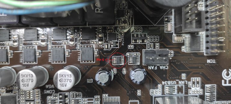
Señalado en el círculo está el uP7536 con problemas internos, el mismo provocaba que el voltaje en el pin 6 disminuyera hasta los 1.2 volts aproximadamente, cuando debería estar en los 3.3 volts aproximadamente que es el voltaje correcto. Esto lo comprobé al realizar la medición con el multímetro
Como no tengo un uP7536 para sustituir el que se encuentra defectuoso, la solución fue aislar el pin 6, para que el nivel de voltaje subiera a los 3,3 volts, ya que se estaban derivando a tierra a través del IC defectuoso. A continuación muestro como lo hice.
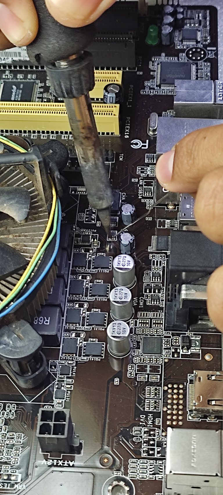
Con ayuda del soldador cautín y un alfiler desoldé el pin 6 y luego levanté dicho pin, aislándolo del circuito impreso
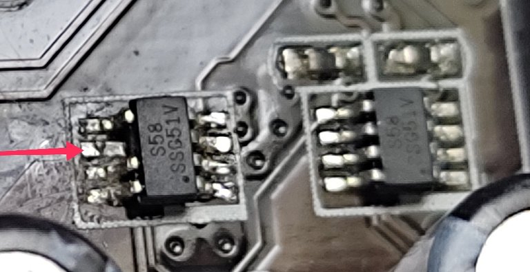
uP7536 defectuoso después de levantar el pin 6 (al levantarlo se partió rasante al cuerpo del IC). Aquí se aprecia que el pin quedó totalmente aislado del circuito
Después de aislar el pin procedí a medir nuevamente el voltaje y el resultado arrojó un valor de 3.4 volt, lo que demuestra que efectivamente el causante de la falla era el IC uP7536 que les mostré anteriormente, el cual, debido a problemas internos, derivaba a tierra una parte de los 3.4 volts.
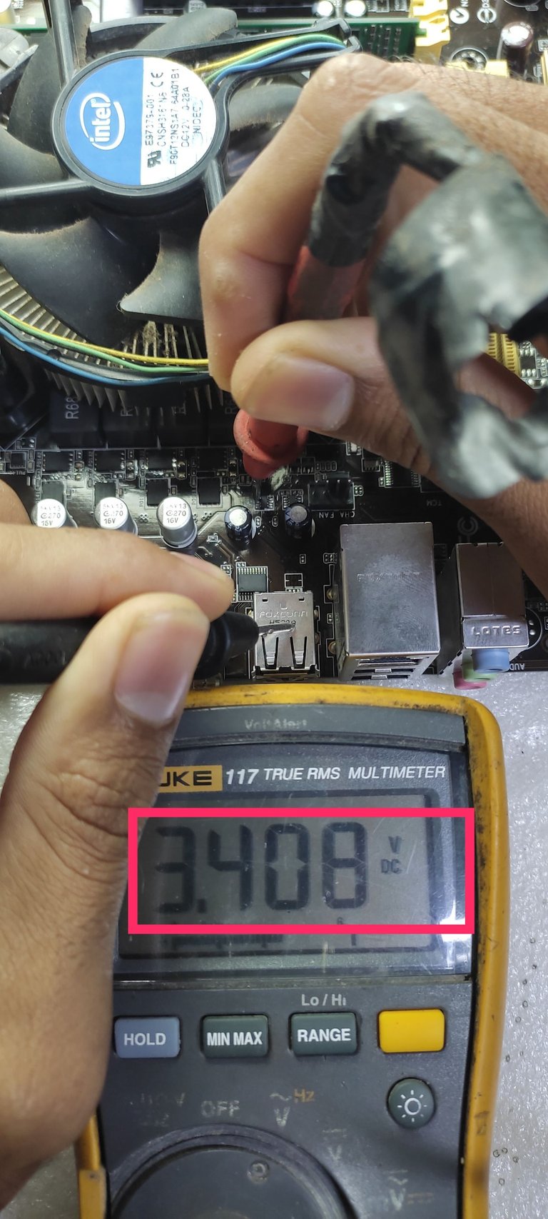
Medición de la señal, la cual arrojó un valor de 3.4 volts, medidos entre el punto de conexión del pin 6 y tierra.
Después de comprobar la presencia de los 3.4 volts en el punto donde va soldado el pin 6, procedí a encender la PC y efectivamente la notificación del error inicial había desaparecido, quedando de esta forma solucionada la falla y la PC operativa nuevamente.
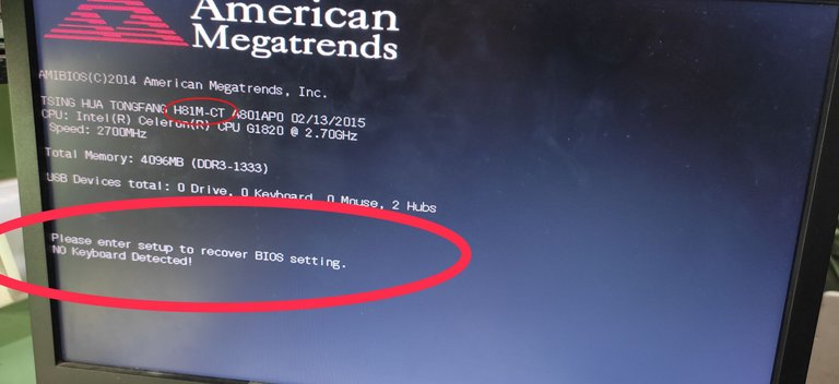
Acá se aprecia que ya la PC inicia correctamente y no está la notificación donde se informa del sobre consumo en el puerto USB.
Cuando este modelo de placa presente esta falla, es probable que le suceda lo que acabo de describir anteriormente y puedes solucionarlo haciendo exactamente todo lo que te comenté anteriormente; sin embargo, recuerda que si quieres aprender a defectar este tipo de problemas en cualquier tipo de placas puedes ver esta publicación en la que doy más detalles al respecto.
A continuación dejaré mis impresiones sobre el funcionamiento del sistema de protección y lo que sucede en el IC durante la falla, basándome en mi experiencia y en lo que he podido averiguar durante el estudio de la literatura.
Les comento que en nuestras PC todos los puertos USB, tienen asociados en la placa un circuito que se encarga de realizar un censado del los 5 volts que presentan, tomando una muestra del mismo y según el valor en el que se encuentre esa muestra, el PCH determina si el puerto USB está en corto circuito o funciona correctamente, en dependencia de esta interpretación se permite el encendido correcto o no de la PC.
Por ejemplo este modelo de placa presenta el Circuito Integrado (IC) uP7536 el cual es un multiplexor de potencia que se usa para la protección de los puertos USB y de la alimentación del sistema, para lograr esto el mismo monitorea constantemente el consumo de corriente en el puerto USB , y si detecta un sobre consumo, internamente activa un interruptor que limita la corriente de salida para proteger la alimentación del sistema. Al mismo tiempo, alerta de que existe un sobre consumo en el puerto USB mediante una señal que es tomada por el pin 6 del IC, dicho pin está conectado internamente a otro interruptor que cuando está cerrado une el pin 6 con el pin de tierra, provocando que el voltaje presente en el pin 6 disminuya, ya que está siendo derivado a tierra.
Estos interruptores internos del IC están confeccionados a base de transistores MOSFET que son controlados por un sistema lógico que está incluido dentro del IC, por lo que la descripción anterior es una explicación Grosso Modo
Esta señal es de aproximadamente 3.3 volts y como mencioné anteriormente es aplicada al pin 6 del IC, al mismo tiempo es aplicada también a unos de los pines del PCH para que pueda ser interpretada por él. Ahora bien, mientras esta señal se encuentre entre los 3 y 3.3 volts, el PCH la interpreta como un funcionamiento correcto del puerto USB. Si el nivel de voltaje de la señal cae por debajo de los 3 volts aproximadamente, pudiera interpretarse como un sobre consumo en el puerto USB, y si está en el orden de 1 volt, la PC no enciende y muestra el error USB Device Over Current Status Detected¡. System Will Shut Down After 15 Seconds, imposibilitando el encendido de la PC.
Conociendo todo esto y a modo de resumen se puede decir que cuando conectamos algún periférico al puerto USB, el uP7536 monitorea el consumo de corriente, si detecta un sobre consumo, el mismo limita la corriente en el puerto para proteger la alimentación del sistema y al mismo tiempo deriva a tierra la señal de 3.3 volts que está presente en el pin 6 provocando que disminuya el voltaje de esta señal y como consecuencia de esto, el PCH interpreta esta disminución de voltaje cómo un sobre consumo en el puerto, evitando que encienda la PC, hasta que se solucione la falla.
Lo que realmente sucede en la Motherboar
Lo que realmente sucede en este modelo de Motherboar es que uno de los seis IC uP7536 suele presentar problemas internamente, lo que provoca falsas interpretaciones. Al parecer suele fallar el mismo IC, el cual activa por error el interruptor que tiene entre el pin 6 y tierra, provocando una disminución de la señal de 3.3 volts que debe de estar presente en dicho pin. Esto lo hace debido a problemas internos que provocan una falsa lectura.
Suele fallar el mismo IC en este modelo de placas base, y la solución a esta falla consiste en eliminar el pin 6 aislándolo de la placa base, de esta forma evitamos que la señal de 3.3 volts se derive a tierra erróneamente.
Cabe destacar que la solución de aislar el pin 6 del IC deja sin protección dos de los puertos USB de la PC, por lo que debe ser tomado en cuanta, y evitar usar esos dos puertos o estar seguros de que el periférico que se conecte en dichos puertos estén en buen estado. La solución ideal sería sustituir el IC si se tuviera el repuesto para hacerlo.
Si has llegado hasta aquí te agradezco por tomarte el tiempo de leer, y si de alguna forma te ha interesado el contenido, pues me satisface saberlo, déjamelo dicho en los comentarios.
Un saludo, y hasta el próximo post 😉.
Las imágenes son de mi autoría y fueron tomadas con un celular Xiaomi Redmi Note 9.
Imágenes editadas en la aplicación "Galería" del teléfono y Canva"*
Puedes verme en Facebook
ENGLISH
Greetings once again to the entire community, I hope and wish that everyone is well at this time.
Today I will be sharing with you how I repaired an Asus Motherboar, model H81M-CT, which presented a fault that is typical in this model, but also usually appears in other models of boards, manifesting in the same way.
The fault I am talking about appears on the Personal Computer (PC) monitor reflected in a notification when we try to turn it on. The notification that appears is as follows: USB Device Over Current Status Detected. System Will Shut Down After 15 Seconds. This message usually appears when we have one of the USB ports short-circuited and with a high current consumption or by a misinterpretation of the PCH or chipset as it is also known. This occurs due to the failure of certain components that cause a misinterpretation. However, this failure in many Motherboar models makes it impossible to turn on the PC completely, leaving it disabled. In this model usually fails an Integrated Circuit (IC) that causes the error mentioned above.
Reference image showing the notification of the error supposedly presented by the board.
This image is of my authorship, but it is the notification of another board with the same error, and I show it as a reference, because I could not take a capture of the error shown by the board I am talking about in this post.
The IC that usually fails is the uP7536 and in this motherboard there are six, of which, regularly fails the same and the solution is to replace the IC, but if you do not have the spare, it is simply solved by removing or isolating the pin 6 of the IC.
Integrated circuit uP7536 with pin identification.
Marked with an arrow, the physical mark identifying pin number 1 is represented.
Marked with a rectangle with rounded ends, pin number 6 is identified, which must be isolated from the circuit.
Asus H81M-CT board with the location of the six uP7536 ICs.
Marked with a yellow circle represents the Integrated Circuit that usually fails and to which pin number 6 must be isolated.
In the following I will explain how I repaired the board, without going too much into the details of the steps and methodology I used to diagnose and repair the failure, because in a publication that I uploaded in the Geek Zone community, I discuss with more elements the methodology and tools needed to diagnose this kind of problems, you can read it if you are interested and want to learn how to repair this specific problem when it occurs in any PC board.
Repairing the failure
First make sure that there is no USB peripheral connected to the board and that the 5 volts are present in all USB ports, this means that there is no short circuit in the USB ports and the problem is due to an IC that usually fails as I mentioned before.
In this model of board it is common that the same IC fails; however, to make sure of it, it is necessary to measure with the multimeter the level of direct voltage that there is in the pin 6 of the uP7536 that I indicated in a yellow circle previously (for this it is not necessary to turn on the pc, only to have it in standby mode), if this voltage is below 2 volts approximately, then the IC must be replaced or isolate the pin No.6 of the circuit. It is valid to measure pin No.6 of the other five uP7536 ICs to make sure they are in good condition, the correct voltage they should have is about 3.3 volts. Later I will explain why this should be the case, and what happens when the voltages are out of parameters.
Signaled in the circle is the uP7536 with internal problems, it caused the voltage on pin 6 to drop to about 1.2 volts, when it should be at about 3.3 volts which is the correct voltage. I checked this by measuring with the multimeter.
Since I don't have a uP7536 to replace the defective one, the solution was to isolate pin 6, so that the voltage level would rise to the 3.3 volts, since they were being shunted to ground through the defective IC. Below I show how I did it.
With the help of the soldering iron and a pin, I desoldered pin 6 and then lifted the pin, isolating it from the printed circuit board.
uP7536 defective after lifting pin 6 (when lifted, it broke off flush with the body of the IC). Here you can see that the pin was completely isolated from the circuit.
After isolating the pin I proceeded to measure the voltage again and the result showed a value of 3.4 volts, which shows that indeed the cause of the failure was the uP7536 IC that I showed earlier, which, due to internal problems, derived to ground a part of the 3.4 volts.
Signal measurement, which yielded a value of 3.4 volts, measured between the connection point of pin 6 and ground.
After checking the presence of the 3.4 volts at the point where pin 6 is soldered, I proceeded to turn on the PC and indeed the initial error notification had disappeared, thus solving the failure and the PC was operational again.
Here you can see that the PC starts correctly and there is no longer the notification informing about the over consumption in the USB port.
When this model of board presents this failure, it is likely that what I just described above will happen and you can solve it by doing exactly what I told you above; however, remember that if you want to learn how to defect this type of problems in any type of boards you can see this publication in which I give more details about it.
Below I will leave my impressions of how the protection system works and what happens in the IC during failure, based on my experience and what I have been able to find out during the literature study.
In our PCs, all USB ports have a circuit associated on the board that is responsible for performing a census of the 5 volts that are present, taking a sample of it and depending on the value in which that sample is found, the PCH determines whether the USB port is short-circuited or working properly, depending on this interpretation is allowed or not the correct ignition of the PC.
For example this board model presents the Integrated Circuit (IC) uP7536 which is a power multiplexer that is used for the protection of the USB ports and the system power supply, to achieve this it constantly monitors the current consumption in the USB port, and if it detects an over consumption, internally activates a switch that limits the output current to protect the system power supply. At the same time, it alerts that there is an over consumption in the USB port through a signal that is taken by pin 6 of the IC, this pin is internally connected to another switch that when closed connects pin 6 with the ground pin, causing the voltage present on pin 6 to decrease, since it is being derived to ground.
These internal switches of the IC are made up of MOSFET transistors that are controlled by a logic system that is included inside the IC, so the above description is a Grosso Modo explanation.
This signal is approximately 3.3 volts and as I mentioned before it is applied to pin 6 of the IC, at the same time it is also applied to one of the pins of the PCH so that it can be interpreted by it. Now, as long as this signal is between 3 and 3.3 volts, the PCH interprets it as a correct operation of the USB port. If the voltage level of the signal drops below 3 volts approximately, it could be interpreted as an over consumption in the USB port, and if it is in the order of 1 volt, the PC does not turn on and displays the error USB Device Over Current Status Detected¡. System Will Shut Down After 15 Seconds, making it impossible to turn on the PC.
Knowing all this and as a summary we can say that when we connect a peripheral to the USB port, the uP7536 monitors the current consumption, if it detects an over consumption, it limits the current at the port to protect the system power supply and at the same time derives to ground the signal of 3. The PCH interprets this voltage decrease as an over consumption on the port, preventing it from turning on the PC until the fault is solved.
What really happens in the Motherboar
What really happens in this model of Motherboar is that one of the six uP7536 ICs usually presents problems internally, which causes false interpretations. Apparently the same IC usually fails, which activates by mistake the switch between pin 6 and ground, causing a decrease of the 3.3 volts signal that should be present on that pin. This is due to internal problems that cause a false reading.
Usually the same IC fails in this model of motherboards, and the solution to this failure is to eliminate pin 6 by isolating it from the motherboard, thus preventing the 3.3 volt signal from being erroneously shunted to ground.
It should be noted that the solution of isolating pin 6 of the IC leaves two of the USB ports of the PC unprotected, so it should be taken into account, and avoid using those two ports or be sure that the peripheral to be connected to those ports are in good condition. The ideal solution would be to replace the IC if you have the spare part to do so.
If you have made it this far I thank you for taking the time to read, and if in any way you have been interested in the content, well I am glad to know, let me know in the comments.
*Greetings, and see you next post 😉.
The images are of my authorship and were taken with a Xiaomi Redmi Note 9 cell phone.
Images edited in the "Gallery" application of the phone and Canva ".
*Text translated to English in Deepl translator.
You can see me on Facebook
This post has been manually curated by @steemflow from Indiaunited community. Join us on our Discord Server.
Do you know that you can earn a passive income by delegating to @indiaunited. We share more than 100 % of the curation rewards with the delegators in the form of IUC tokens. HP delegators and IUC token holders also get upto 20% additional vote weight.
Here are some handy links for delegations: 100HP, 250HP, 500HP, 1000HP.
100% of the rewards from this comment goes to the curator for their manual curation efforts. Please encourage the curator @steemflow by upvoting this comment and support the community by voting the posts made by @indiaunited.
Thanks for the support. Merry christmas.
¡Felicitaciones!
1. Invierte en el PROYECTO ENTROPÍA y recibe ganancias semanalmente. Entra aquí para más información.
3. Suscríbete a nuestra COMUNIDAD, apoya al trail de @Entropia y así podrás ganar recompensas de curación de forma automática. Entra aquí para más información sobre nuestro trail.
4. Creación de cuentas nuevas de Hive aquí.
5. Visita nuestro canal de Youtube.
Atentamente
El equipo de curación del PROYECTO ENTROPÍA
Gracias por el apoyo. Feliz navidad a todo el equipo
Congratulations @darknapol! You have completed the following achievement on the Hive blockchain And have been rewarded with New badge(s)
Your next target is to reach 2250 upvotes.
You can view your badges on your board and compare yourself to others in the Ranking
If you no longer want to receive notifications, reply to this comment with the word
STOPCheck out our last posts:
Thank you for sharing this well detailed repair work. Surely someone would find it useful.
I imagine that yes, that it could be of use to someone, that is one of my intentions with the publication, I like to clarify as much information as possible so that it serves each person to the extent possible the knowledge you have. Thanks for comment, . Merry Christmas to the Diyhub team.
Thank you very much for the support, it is a pleasure to be part of the hivediy Community.