In 1831, Michael Faraday discovered electromagnetic induction, which enabled him to transfer electrical power from one circuit to another by varying the magnetic linkage. Faraday’s discovery led to the large-scale generation and distribution of electrical energy that transformed society and industry, as this energy could now be delivered to homes, hospitals, schools, and factories many miles from the source. Over 150 years later, new applications of electromagnetic induction are still being developed.

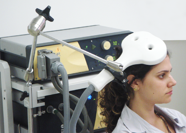
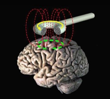
A magnetic coil positioned at the head of the person. Baburov, CC BY-SA 4.0
Induction cooking is faster and more energy efficient than more traditional hobs, with the added advantage that less heat is lost to the surroundings and it’s fairly simple to monitor changes in resistance so that cooking rings can be turned off automatically if pans boil dry or spill over.
Tiny currents induced in brain tissue can be used to monitor brain activity and this offers a non-invasive way of treating many disorders including depression. It’s called Transcranial Magnetic Stimulation. Linear induction motors have become established in some of the fastest train systems on Earth. Magnetic levitation enables near-frictionless motion and the Japanese MLX-01 reached a speed of 581 km/h in 2003. There were plans to link Edinburgh and Glasgow with a Maglev link, which would make it possible to travel from city centre to city centre in 15 minutes.
‘Induction Loop Systems’ are now widely used to enable people with hearing impairment to hear more clearly. These systems are used in the home and in public places such as theatres and cinemas. These are just some examples of how Faraday’s discovery in 1831 has been applied in today’s world.
The ideas in this post
This post is about electromagnetic induction. This was Michael Faraday’s amazing discovery on the 29 August 1831, which led to the birth of the electrical industry.
Today we are surrounded by devices and gadgets that use electricity. Try to imagine life without ‘electricity’. Many devices use batteries as a source of energy but most rely on ‘mains’ electricity. That is, electricity that is induced or generated in power stations. By the start of the twenty-first century, Britain’s power stations were producing nearly 60 gigawatts (6 x 10⁹ W) to cope with the demands of modern society and industry.
Induced currents have many other applications, ranging from car speedometers to domestic cookers that induce currents in the base of cooking pans. Induction heating is extensively used in industry, while the most common motor used for driving all sorts of machinery is the induction motor.

WHAT IS ELECTROMAGNETIC INDUCTION?
Michael Faraday’s discoveries early in the nineteenth-century have made the large-scale production of electrical energy possible. The date 29 August 1831 is acknowledged as the ‘birth of the electrical industry’ – the day on which Faraday discovered electromagnetic induction. He made the link between electricity and magnetism when he showed that an electric current was produced when a magnet was moved near to a conductor (a metal wire).
Simple experiments provide the evidence. A magnet is moved into and out of a coil connected to a galvanometer, as shown in the figure below, and a current is observed whenever the magnet moves (or, if the magnet is kept stationary, whenever the coil moves). A wire moved through a magnetic field produces the same result.

Faraday's experiments on induction. Wellcome Images, CC BY-SA 4.0
Faraday’s experiments also led to the first simple transformer. He wound two coils on an iron ring. One, the primary coil, was connected to a battery and the other, the secondary coil, to a galvanometer. The galvanometer showed a current in the secondary coil only when the current from the battery was switched on or off: that is, only when the current from the battery, and hence the magnetic field, was changing.
So, a current is induced whenever a wire in a closed circuit moves through a magnetic field or when the field changes through the wire. The following helps to explain the important ideas in more detail:
- The rigid straight wire XY moves with a velocity v perpendicular to a uniform magnetic field of strength B tesla. The wire is l m long.
- There is a force on the electrons in the moving wire (evB, where e is the charge on a charge carrier, and free electrons will move towards end X of the wire. As they build up at X, so does an electric field that opposes the movement of electrons (just as in the Hall effect.
- Eventually, the electric force is equal to the magnetic force:
eE = evB
where E is the electric field strength. We can also write:
E = V/l
Where V is the final voltage induced across the ends of the wire.
- This ‘voltage’ is an induced e.m.f., since it is the movement of the wire through the field that produces charge separation.
- Putting this together we have:
E V/l = evB
Or:
V = Blv
- Thus the induced e.m.f. V is proportional to the magnetic flux density B, the length of the conductor and the speed at which it moves. (Note that if the conductor is at an angle θ to the field the induced voltage is V = Blv sin θ.)
THE INDUCED CURRENT
Once the e.m.f. is established, no more charge flows because the electric force is equal to the magnetic force. What happens when the wire is part of a complete circuit? To answer that, suppose the wire XY runs along two rails that are part of a simple circuit with a total resistance of R ohms and a uniform magnetic field B. The induced e.m.f. will drive a charge around the circuit. The direction of the ‘conventional’ current is shown.
Now that there is a current (charge flowing), a force (IlB) affects the wire because it is in a magnetic field. This force acts in the opposite direction to the way the wire is moving. To keep the wire moving at a constant velocity v, a force equal to this must be applied in the direction of the movement. In t seconds the wire moves to X’Y’ a distance of vt metres. The work done in moving the wire is given by:
work done = force × distance moved
= IlB × vt
Since energy must be conserved, the work done is equal to the electrical energy transferred in the circuit:
Electrical energy supplied = power × time
= IV × t
where V is now the p.d. across the load R. Therefore, we can write:
Ivt = IlBvt
or:
V = Blv
What this tells us is that V, the induced e.m.f., is the same, whether a current is drawn or not.
TOWARDS A MORE GENERAL LAW
With the help of the figure, we can look at this result in a slightly different way. When the wire XY moves it sweeps through an area of (vt × l), so vl is the area swept through per second:
vt × l/t = vl = dA/dt
Where dA/dt is the rate of change of area.
We can now write the equation for the induced e.m.f. as:
V = B dA/dt
That is, the induced voltage is equal to the flux density of the field multiplied by the rate at which the area swept through changes. Faraday reached the same result, but he used the idea of flux.
EXAMPLE
A 10 cm wire is moved perpendicular to a steady magnetic field of flux density 5 mT at a speed of 0.5 ms-1. Calculate the rate of change of the area that the wire sweeps through, and the induced e.m.f.
ANSWER:
Speed of wire × length = dA/dt = vl
= 0.5 ms-1 × 0.1 m
So rate of change of area = 0.05 m2s-1
V = B dA/dt
= 5 × 10-3 × 0.05 = 0.25 × 10⁻³ V
So induced e.m.f. = 0.25 mV
FARADAY’S LAWS OF ELECTROMAGNETIC INDUCTION
After careful experiment, Faraday set out his laws of electromagnetic induction. For a wire moving through a magnetic field he found that the size of the induced e.m.f. is proportional to: the strength of the magnetic field, the speed at which the wire cuts the field, the number of turns of wire (as part of a coil, for example).
FLUX CUTTING AND FLUX LINKING
The action of a wire being passed through a field is often referred to as ‘flux cutting’. Faraday’s ‘transformer’ experiments, however, do not involve moving wires. A current is induced in a secondary coil when the current in primary coil changes. The current in the primary produces a magnetic flux which links with the secondary coil. When this flux changes, a current is induced in the secondary coil. This is called flux linking’. The induced current is proportional to: the strength of the field, the rate of change in the flux produced by the primary coil, the number of turns, N, on the secondary coil.
To induce a continuous current in the secondary, then, the current in the primary must continually change. For instance, if it is an alternating current (a.c.), then the induced current will also alternate. The induced current will also depend on the a.c. frequency. An increase in frequency means that the flux is changing over a shorter time; that is, the rate of change of flux increases and the induced current is larger.
Conversely, if the frequency of the a.c. in the primary is reduced, the flux changes over a longer time, so this reduces the rate of change of flux and the induced current: the size of the induced current in the secondary coil is proportional to the frequency of the alternating current in the primary coil.
Faraday’s laws can be summarised in one statement: The induced e.m.f. is proportional to the rate of change of flux or, if ɛ is the induced e.m.f.:
ɛ = N dφ/dt
where N is the number of turns of wire.
The equation could also be written as:
ɛ = d (Nφ)/dt
The quantity Nφ is called the flux linkage and is used when a particular coil with N turns is considered.
LENZ’S LAW
When the north pole of a magnet is pushed into a coil, the direction of the induced current creates another ‘north pole’ at the end of the coil because the current ‘opposes’ the approaching north pole. When the magnet is removed, the direction of the induced current is reversed, changing the end of the coil to a south pole. This again opposes the north pole, which is now leaving the coil.
Lenz’s law states: The direction of the induced current opposes the change that causes it.
Lenz’s law is the ‘electromagnetic’ version of the law of conservation of energy. If Lenz’s law were not true, energy would not be conserved. To show that the effects are opposed, we introduce a negative sign. The equation for the induced e.m.f. then reads:
ɛ = -N (dφ)/dt
THE TRANSFORMER
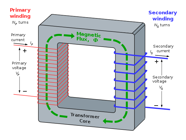
It has been shown that loops of current create loops of magnetic flux. Faraday showed us that loops of changing flux can create loops of current. Magnetic circuits link with electric circuits.

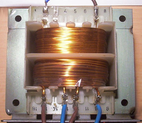
Transformer. Stefan Riepl (Quark48) , Public Domain
The transformer is an example where the magnetic circuit links two electric circuits. Faraday’s original experiments demonstrated the action of the transformer. If the current in the primary coil is continually changing, then the flux it produces will also change continuously. The flux path, through the transformer core, is at right angles to the primary current path. The flux path also cuts the secondary coil at right angles. The changing flux induces a continually changing current in the secondary.
If the voltage applied to the primary is sinusoidal then the e.m.f. induced in the secondary will also be sinusoidal; that is an alternating voltage. An alternating voltage of Vp is applied to the primary which has Np turns and resistance Rp ohms. The alternating voltage drives a current Ip which creates a flux in the core. The flux induces an e.m.f. in the secondary, but it also induces an e.m.f. in the primary. The ‘primary’ e.m.f. opposes the applied voltage so that:
Vp - Np dφ/dt = IpRp
If the core is short and fat then a small current will produce a large flux, and if the resistance of the primary coil is low then:
Vp = Np dφ/dt
If there are Ns turns on the secondary then the voltage induced in it, Vs will also be linked to the changing flux:
Vs = Ns dφ/dt
If we divide Vs by Vp, the flux and its rate of change through each coil is the same. This leaves us with a very useful relationship for transformers:
Vs / Vp = Ns / Np
The ratio Ns/Np is called the turns ratio of the transformer and the equation shows it is approximately equal to the ratio of the secondary primary voltages. This is very useful if you are designing transformers.

Ideal transformer and induction law. BillC, CC BY-SA 3.0
Transformers have many applications over a wide range of a.c. frequencies. They are used to step-up and step-down voltages in power supplies and they are essential in the National Grid, which will be discussed in the next post.
REFERENCES
https://www.techopedia.com/definition/19997/electromagnetic-induction
https://www.electronics-tutorials.ws/electromagnetism/electromagnetic-induction.html
https://en.wikipedia.org/wiki/Electromagnetic_induction
https://www.classe.cornell.edu/~liepe/webpage/docs/Phys2208_lecture20.pdf
https://www.rpi.edu/dept/phys/ScIT/InformationStorage/faraday/magnetism_a.html
https://nationalmaglab.org/education/magnet-academy/watch-play/interactive/induced-current
https://www.quora.com/What-is-an-induced-current
https://www.daenotes.com/electronics/basic-electronics/faraday-laws-of-electromagnetic-induction
https://en.wikipedia.org/wiki/Faraday%27s_law_of_induction
https://www.electrical4u.com/faraday-law-of-electromagnetic-induction/
https://en.wikipedia.org/wiki/Flux_linkage
https://physics.stackexchange.com/questions/116983/flux-cutting-and-flux-linking
https://byjus.com/physics/lenzs-law/
https://www.britannica.com/science/Lenzs-law
https://en.wikipedia.org/wiki/Lenz%27s_law
https://www.electrical4u.com/what-is-transformer-definition-working-principle-of-transformer/
https://www.electronics-tutorials.ws/transformer/transformer-basics.html
https://en.wikipedia.org/wiki/Transformer
Nice post. Remember my University times :)
Congratulations @emperorhassy! You have completed the following achievement on the Steem blockchain and have been rewarded with new badge(s) :
You can view your badges on your Steem Board and compare to others on the Steem Ranking
If you no longer want to receive notifications, reply to this comment with the word
STOPTo support your work, I also upvoted your post!
Do not miss the last post from @steemitboard:
This post has been voted on by the SteemSTEM curation team and voting trail. It is elligible for support from @curie and @minnowbooster.
If you appreciate the work we are doing, then consider supporting our witness @stem.witness. Additional witness support to the curie witness would be appreciated as well.
For additional information please join us on the SteemSTEM discord and to get to know the rest of the community!
Thanks for having used the steemstem.io app and included @steemstem in the list of beneficiaries of this post. This granted you a stronger support from SteemSTEM.