What Will I Learn?
In this tutorial the user will learn:
-Fritzing for Arduino applications in protoboard and schematic.
-Design of an alarm based on an analog input.
-Connection of the input and output ports of the Arduino Uno.
Requirements
-Basic knowledge of Arduino programming.
-Basic knowledge of electronic devices.
-2 220 Ohm resistors.
-1 potentiometer of 10k Ohm.
-2 leds
-Arduino Uno Card
Difficulty
- Intermediate
Tutorial Contents
Greetings, this is a contribution from @gasuba for Utopian from the Open Source line. A connection to the Fritzing program is presented using the Arduino Uno platform for the acquisition of an analog signal, in which example we will use a potentiometer, bearing in mind that this input can resemble any analog input such as: temperature, LDR, pressure and other sensors that we want to connect in the entrance of this card.
In this design we will work with basic electronic components and we will incorporate a card based on an Atmega microcontroller, this with the purpose of adding a degree of decision power to our programming circuit of the Arduino card.
For this design we will work with a potentiometer, resistors, two leds and Arduino Uno card. The circuit will consist of the control of an alarm for a potentiometer value programmed in Arduino, in this way when the potentiometer delivers a value of 2.5V to the analog input port of the Arduino Uno card, the green colored LED will light, and otherwise the red led will light up.
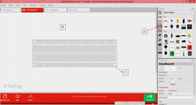
N°1. When opening the fritzing program we will see:
A. Zone to locate the Arduino One card and different types of modules that are associated with this
card.
B. Fritzing work area, to incorporate the components for the design that we are going to carry out.
C. Protobard to connect the electronic components to be used.

N°2. We proceed to add the Arduino Uno card:
A. Deployment of components where the Arduino card is located.
B. Plate inserted into the breadboard.

N°3. In the item called "A", you will find all the electronic components that we will use in the design:
B. Two 220Ω resistors to connect with LEDs.
C. Two LEDs as indicators of alarm status.
D. Potentiometer to regulate the analog signal that will be sent through the Arduino board.

N°4. For the configuration of the properties of the electronic elements we select the device, in my case select the resistance and I went to the properties: tolerance, resistivity among other characteristics of the resistance, these parameters can be modified in the color box that is It shows in the following window.

N°5. We select the A1 analog pin of the Arduino, we wire to the pin of the middle of the potentiometer, while the other two pins of the potentiometer we place it in 5V and Ground. We wired the pins 11 and 12 of the Arduino to each resistor, and this to the anode of the LEDs and the cathode connected to the ground, in addition the pin GND of the Arduino also connected to the common ground of the circuit, as shown in the following figure:

N°6. We are located in the Schematic tab, in order to see the drawing of the circuit which we designed:

We accommodate each component of the circuit to understand the operation of the circuit in a more readable way:

N°7. Once the circuit connection is complete, proceed to record the following code on the Arduino Uno board:
float v;// Declare variables to be used within the program as floating
float Led; //Declare variables to be used within the program as floating
void setup()
{
//The output ports to be used are configured
  pinMode(11, OUTPUT);
  pinMode(12, OUTPUT);
 Serial.begin(9600); //The communication is initialized in Serial Monitor
}
void loop()
{
    v=analogRead(x); //The variable "v" takes the read value of the port named "x"
  Led=v /204,5; //Equivalence of the analog value of the potentiometer to voltage of 0 at 5V
  Serial.println(v);
  Serial.println(Led);// Print the input voltage values
  if(Led<2.5){
//Voltage value to activate the alarm with the green LED.
  digitalWrite(12, HIGH);
  digitalWrite(11, LOW);
  delay(1000); // Wait for 1000 millisecond(s)
  }
    else{
//Voltage value to turn off the alarm with the red LED.
  digitalWrite(12, LOW);
    digitalWrite(11, HIGH);
  delay(1000); // Wait for 1000 millisecond(s)
   }
  }
N°8. Actual operation of the circuit connection made in fritzing:
When the alarm is activated, the green LED lights up

Deactivating the alarm turns on the red LED:

Thank you all for your attention, I hope it will be very useful ... See you in the next tutorial.
Posted on Utopian.io - Rewarding Open Source Contributors
Thank you for the contribution. It has been approved.
You can contact us on Discord.
[utopian-moderator]
Hey @gasuba I am @utopian-io. I have just upvoted you!
Achievements
Suggestions
Get Noticed!
Community-Driven Witness!
I am the first and only Steem Community-Driven Witness. Participate on Discord. Lets GROW TOGETHER!
Up-vote this comment to grow my power and help Open Source contributions like this one. Want to chat? Join me on Discord https://discord.gg/Pc8HG9x
Que buena publicación. Mis más sinceras felicitaciones. Te dejo mi humilde voto. Exito
Excellent tutorial @gasuba.